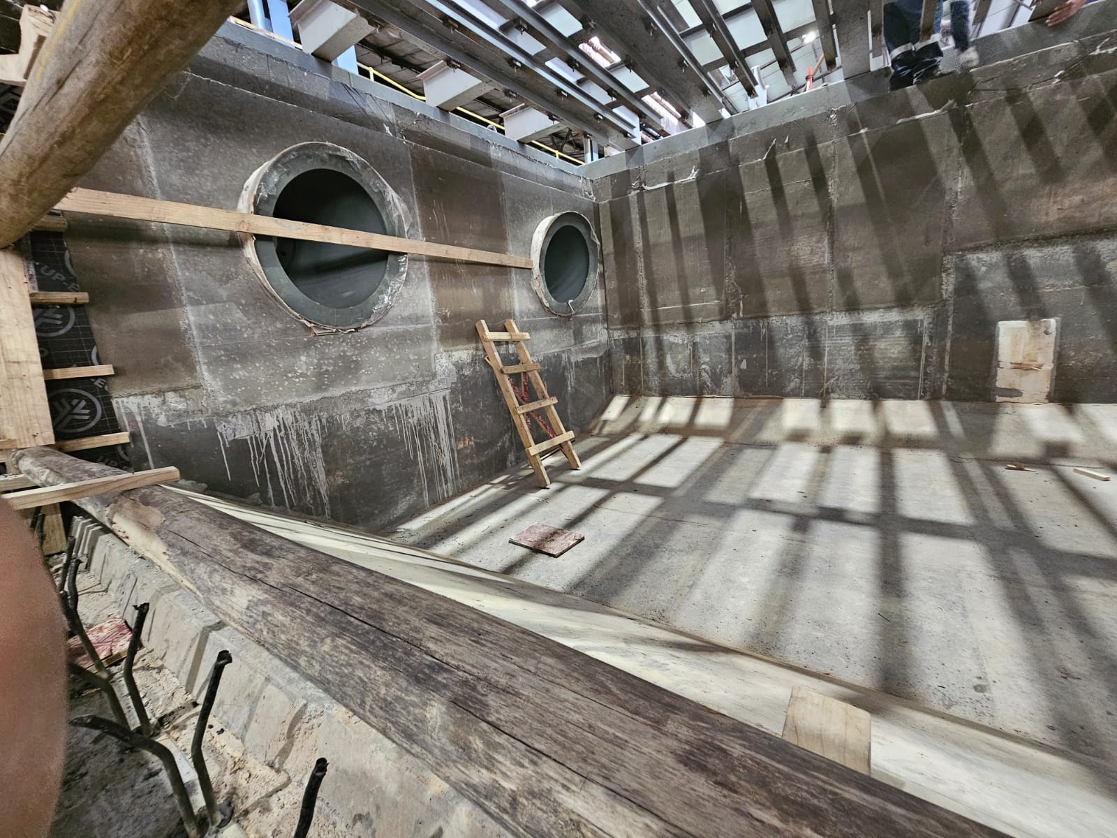
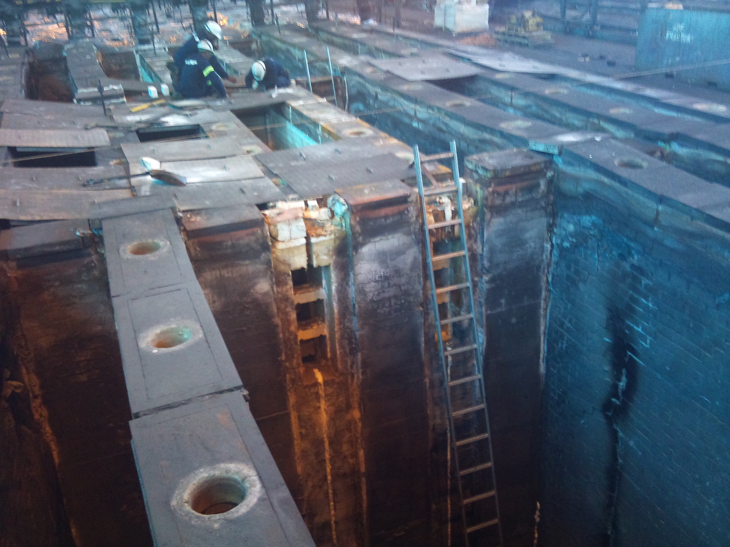
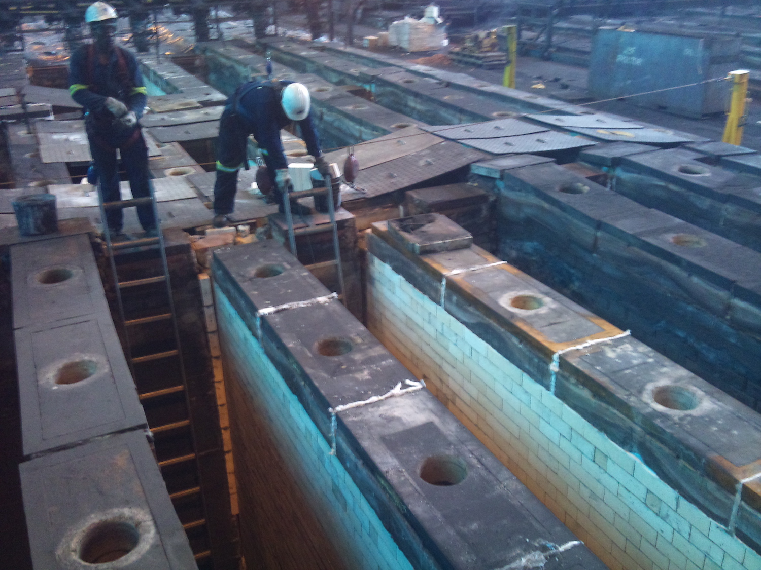
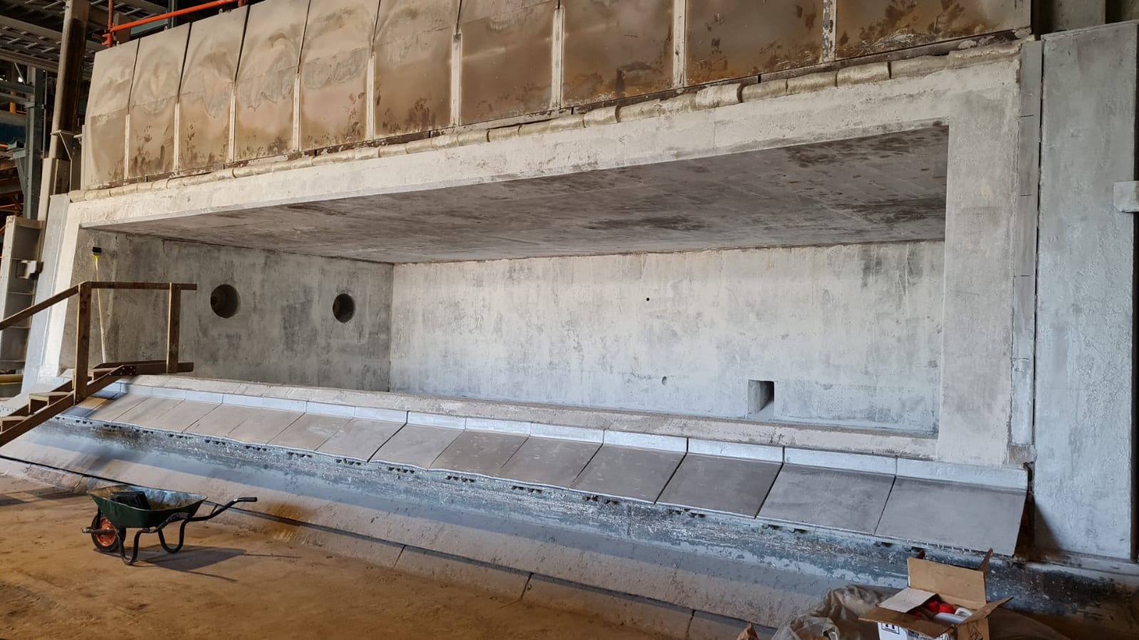
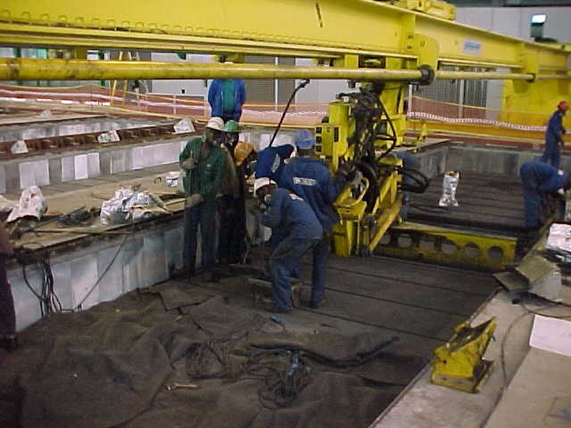
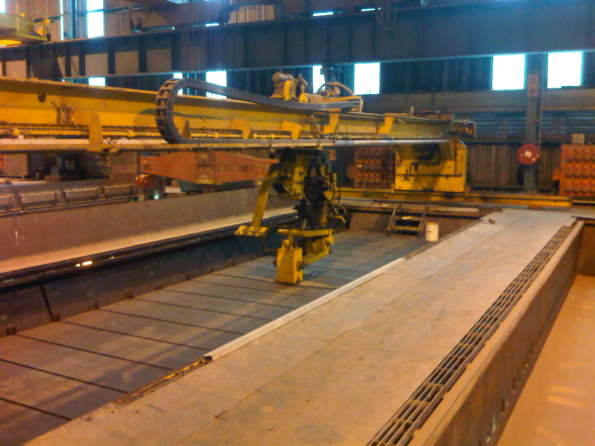
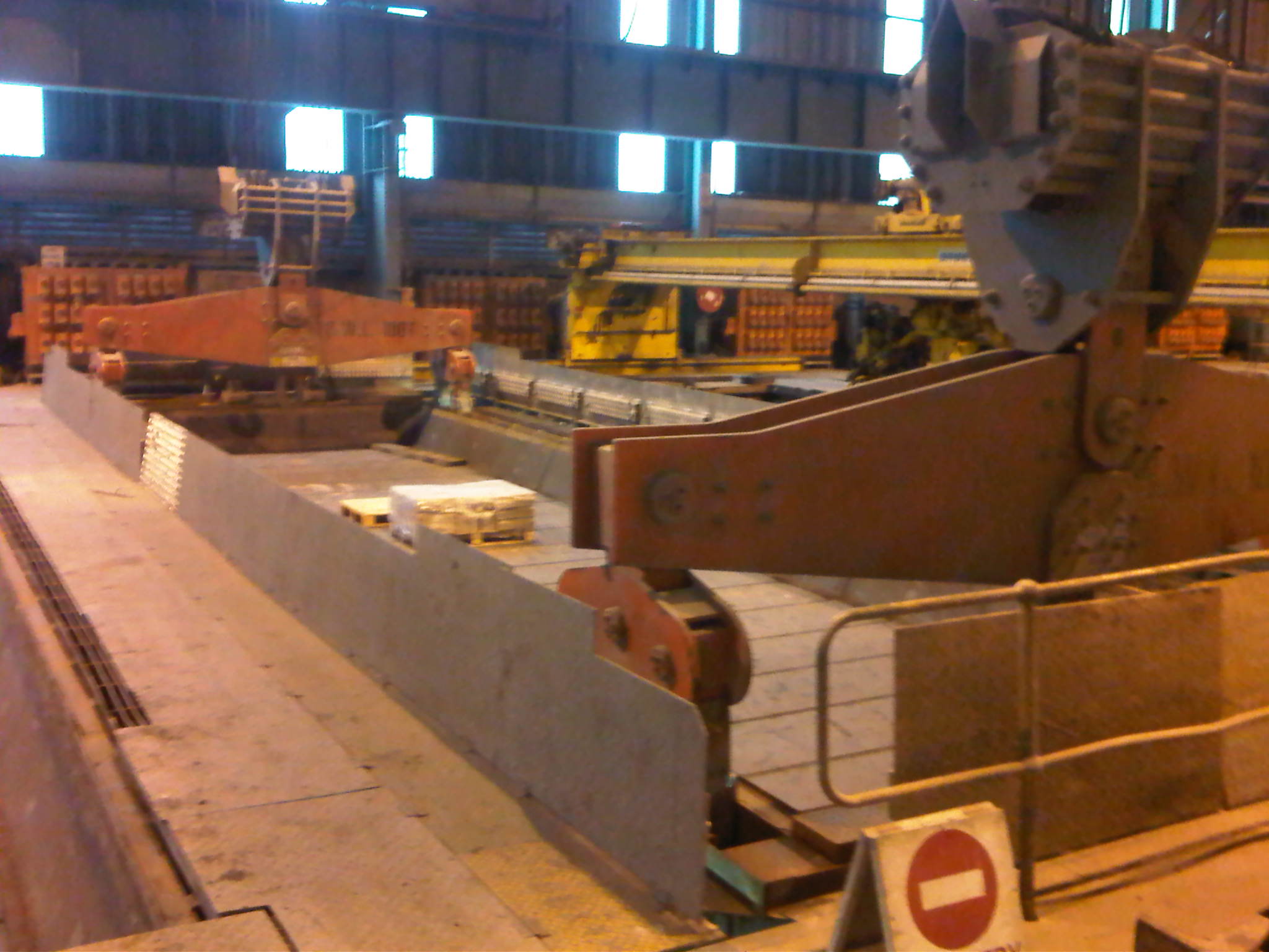
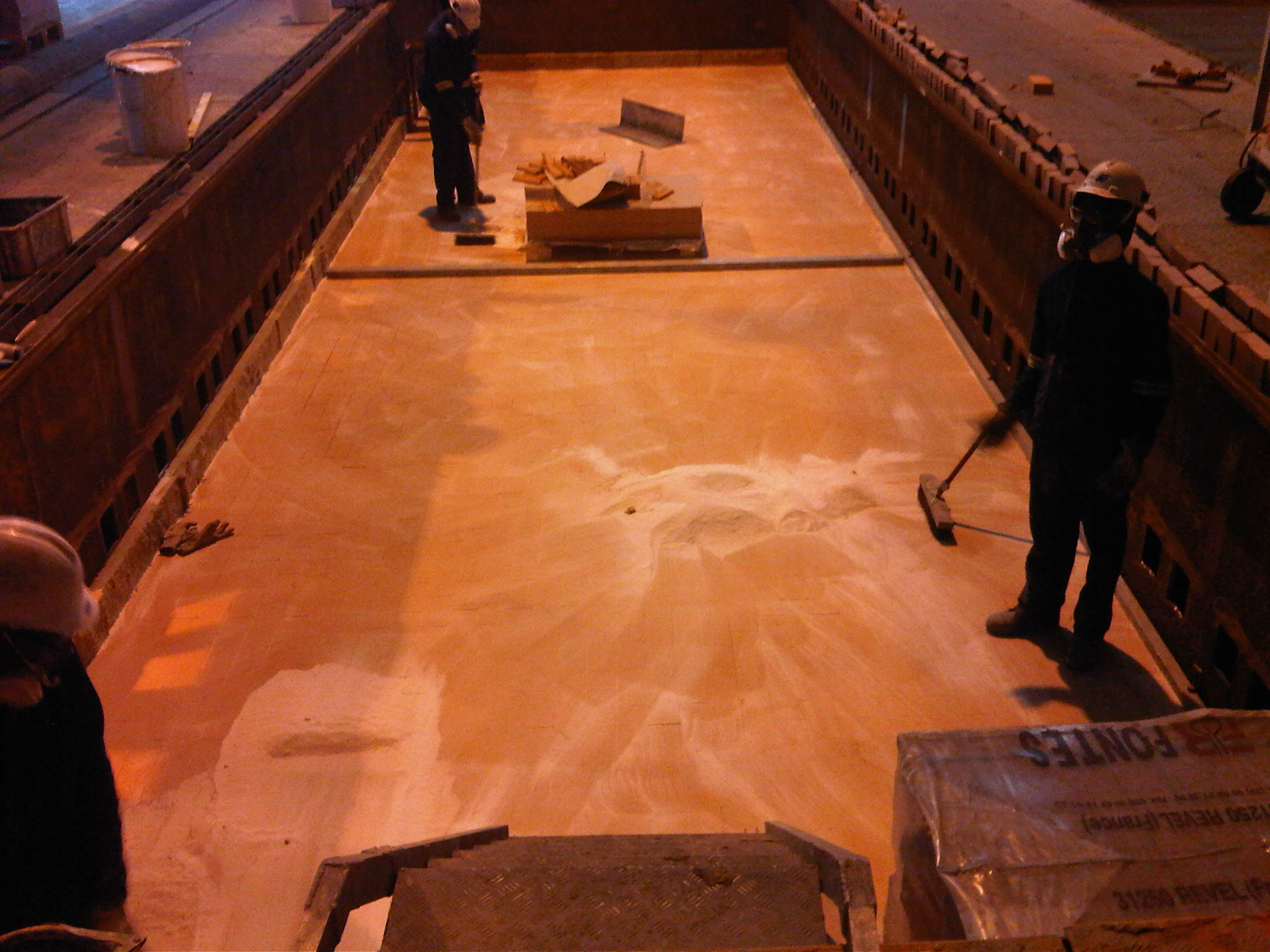
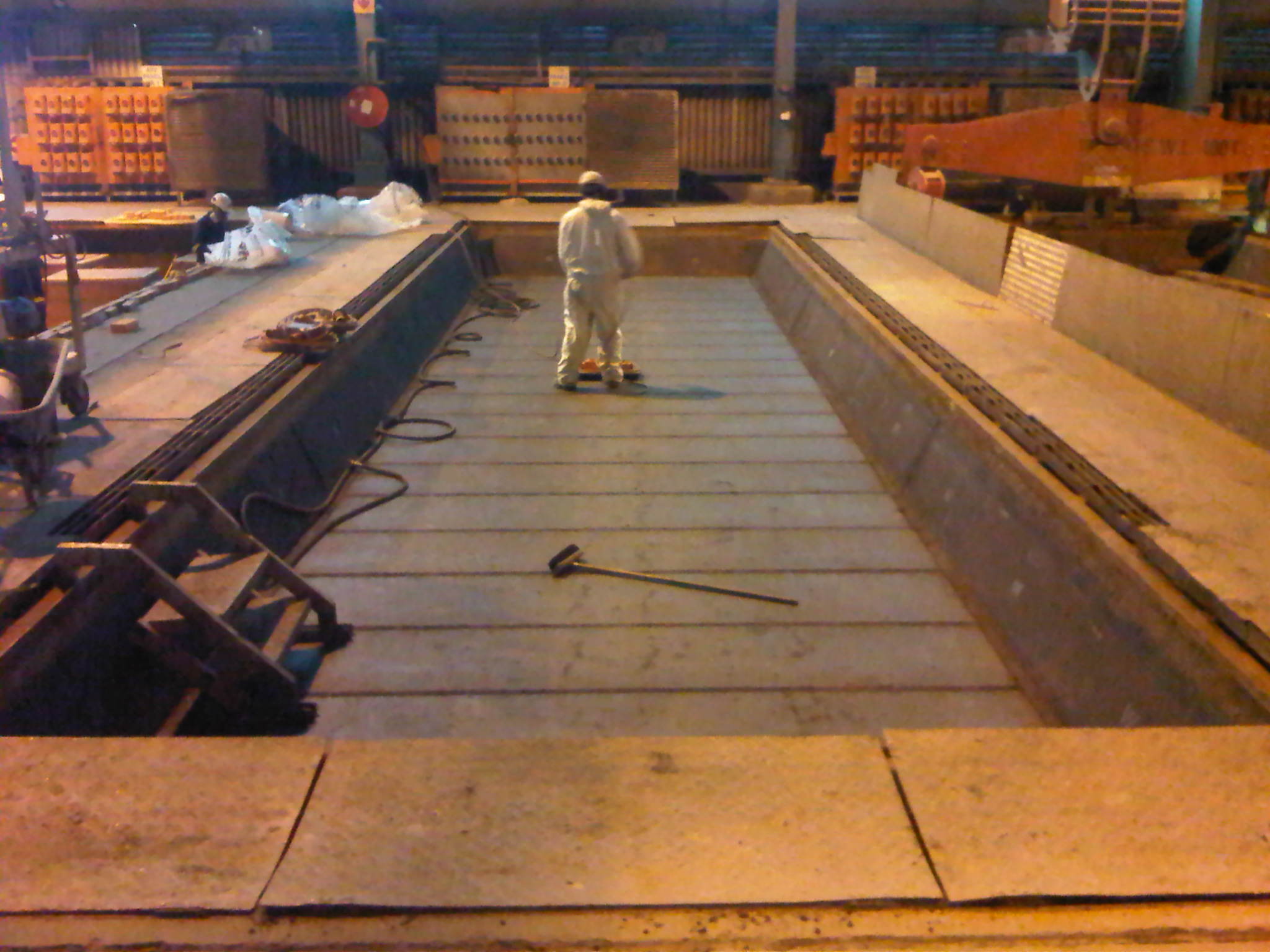
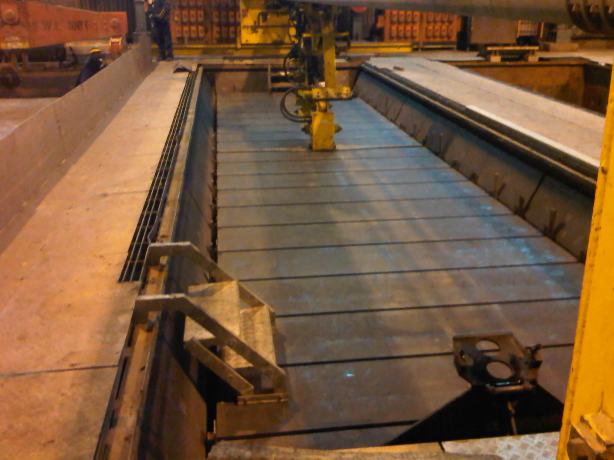
Aluref’s pot shell relining process incorporates a carefully controlled sequence of refractory installation activities. Each stage contributes to the thermal performance, structural integrity and operating life of the aluminium reduction cell.
Step 1 – Bottom Brickwork
The bottom brickwork is installed between the bottom steel plate of the pot shell and the cathode blocks.
The refractory design and installation must maintain the required heat gradient through the bottom of the pot to prevent excessive heating or cooling of the cathode blocks.
The refractory system must also provide resistance against sodium and fluorinated product attack and minimise the risk of molten aluminium penetration through the cathode system. This protection is essential to prevent damage to the bottom steel plate and potential pot shell burn-through.
Step 2 – Cathode Block Installation
The cathode system consists of 20 sealed cathode blocks installed on an alumina bed.
The cathode blocks provide the primary electrical conduction path within the reduction cell while also forming a critical barrier against the penetration of liquid bath and molten aluminium into the underlying refractory system.
Accurate positioning, alignment and installation of the cathode blocks are essential to ensure the required electrical and mechanical performance of the finished pot.
Step 3 – Upper Brickwork
The upper brickwork is constructed in two separate stages:
- Head upper brickwork and Castable – normally completed before the cathode block installation.
- Long-side upper brickwork – completed after the cathode blocks have been installed.
The upper brickwork forms an important part of the pot’s refractory protection system and must be installed accurately to achieve the required dimensions, thermal performance and mechanical integrity.
Step 4 – Ramming of Small and Large Joint
This operation involves filling the joints between the individual cathode blocks and the larger gaps between the cathode blocks and preformed blocks using lining paste.
The process includes:
- Small joints – gaps between adjacent cathode blocks.
- Large joints – spaces between cathode blocks and preformed blocks.
Joint quality is one of the most critical factors influencing the operating life of a pot. The joints must provide the required seal-tightness and mechanical resistance while preventing pathways for molten material penetration.
Step 5 – Sealing Box Filling
The sealing boxes are filled using a purpose-designed injection machine for KUB concrete. The stuffing boxes are welded to the external walls of the pot shell.
The sealing system provides tightness around the cathode bar outlets by injecting KUB concrete into the external sealing boxes and into the internal sealing area of the pot shell.
The internal sealing area is prepared during the side-wall brickwork installation and through the casting of refractory material between the cathode bars.
Correct preparation, injection and compaction of the KUB concrete are essential to achieving an effective seal around the cathode bar outlets and protecting the pot shell from potential penetration and leakage.
Quality and Process Control
Each stage of the pot relining process requires controlled installation, dimensional checks and quality inspections. Accurate refractory installation is essential to achieving the required thermal characteristics, electrical performance, sealing integrity and service life of the completed reduction cell.